The Merlin was a petrol engine, which in a car or an aeroplane has to have many cylinders to make it run smoothly and powerfully. A single cylinder is OK for a small bike, and you can hear how rough and vibratory they are! In my book I take you through the whole engine, piece by piece.
There are 12 cylinders in a Rolls-Royce Merlin engine, arranged in a Vee-shape. Each one had a capacity of 2.25 litres- that’s more than a Series II Land Rover engine!
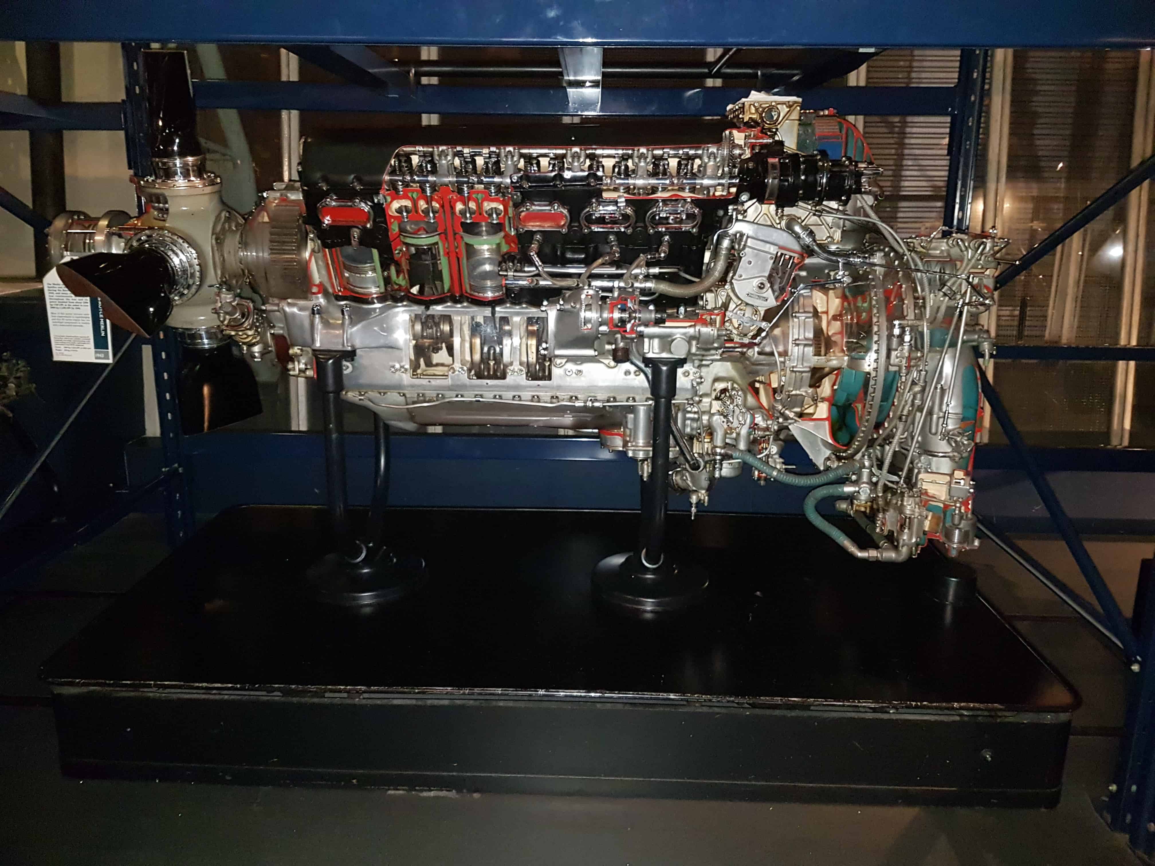
Let’s look at a Merlin III, an early variant that fought in the Battle of Britain, made in the Derby Rolls-Royce factory and delivered in July 1938. It’s about the size of an office desk. The twelve cylinders are arranged in two banks of six, which are mounted on an alloy crankcase at an included angle of 60 degrees. The banks are denoted A for starboard and B for port. They are cooled by a mixture of glycol and water, so there are no cooling fins visible.

In this Merlin III the cylinder blocks and heads are still cast together in a monoblock arrangement, but we know that later versions separated these. The cylinder liners are wet; that is, they are in direct contact with the coolant and so the exterior of each liner is nickel plated to resist corrosion. There is a seal recessed into a circular groove around the combustion chamber that mates with the top of the liner, and this has to keep in the high-pressure gases of combustion and keep out the boiling coolant. It is this seal that caused problematic leaks. The liners are almost totally sunk into the block, a small protrusion locating them in the spigoted circular holes in the crankcase.

At this point spare a thought for the poor fitters. When a leaky Merlin came in, boiling coolant spurting everywhere, they had to replace these seals. The same procedure had to be followed as on the winning Supermarine S6B in 1931: the combined cylinder block and head had to be lifted off the fourteen studs and six pistons, the seals replaced, then the whole heavy lump carefully slid down over the pistons, immense care being taken not to break the brittle piston rings.
The crankcase is the long shiny casting at the bottom that contains and supports the crankshaft. It is made of RR50, an aluminium-nickel alloy developed by Rolls-Royce. The forward part of the crankcase forms the rear half of the propeller reduction gear casing. It has twelve large circular holes bored in in it to take the bottom of the liners, and a forest of 28 long studs to hold down the cylinder blocks.
Inside the crankcase are partitions or internal webs which are bored to support the crankshaft. Each bearing journal takes plain half-shell lead-bronze bearings which support the crankshaft, which spins at up to 3,000 revolutions per minute, or 50 times a second. The centre bearing has to support a load of 14 tons at full power.
The bottom half of the crankcase looks rather like the sump of your car engine, if you peer underneath. It is an alloy bathtub which is usually filled with hot oil draining from the engine. It has two oil pumps in it; a scavenge pump to retrieve the oil and pump it to the oil tank, and a pressure pump to force the cooled oil back around the engine. The oil tank contains enough oil to lubricate the engine for a short time when it is flying upside down or experiencing negative g. Two brass plates on the left or port side inform us of the engine data and the cylinder firing order, so we know which Merlin this is.
The crankshaft is the heart of the engine. The Merlin crankshaft began life as a 500-pound chrome moly steel forging and when it was finished it weighed just 120 pounds. Every ounce had to be machined away by hand on manually operated lathes and mills in 140 separate operations. The machinists were very often women. It had been machined all over, heated up and then nitrogen hardened. It has six balanced throws for six pairs of connecting rods.
Car mechanics would find it strange that the crankpins are hollow and capped, but they would be familiar with the fact that the crankshaft is drilled throughout its length. This allows the passage of high-pressure oil which lubricates the main bearings and the big-end bearings which are mounted on the crankpins. At the front the crankshaft drives the propeller reduction gear and at the rear it drives the supercharger.

The steel connecting rods would be strange to a car mechanic, too, but perhaps not an historically minded marine engineer. They are arranged in pairs; one of them a forked rod and one a plain rod. The plain rod is assigned to cylinder bank A and it runs on a bearing contained in the forked rod, assigned to bank B. This bearing in turn runs on a crankshaft crankpin. The top ends of the rods carry the gudgeon pins in a bronze bush. These pins connect the rods to the pistons as wrists connect your arms to your hands.
The pistons are forged from another Rolls-Royce aluminium alloy: RR59. There are five grooves machined in each one containing, from the top: three compression rings to seal in the gases of combustion; these are made of hard-wearing cast iron. Below these is a spring-steel oil-scraper ring, which has to scrape excess oil from the cylinder bore. It has holes in it to allow the oil to flow back inside the piston.
Finally, beneath the gudgeon pin there is another oil scraper ring. When desert sand wore out the Merlin engines in the campaign against Rommel, it was these rings which wore out and let oil up into the combustion chambers, resulting in blue smoke, which is the sure sign of a worn-out piston engine the world over.
The combustion chambers are formed inside the one-piece cylinder blocks and cylinder heads. They contain two inlet valves and two exhaust valves. These are forged from austenitic nickel-chrome steel: what we would call stainless steel. As we have seen these started off in earlier engines looking like a penny on a stick. As they glowed red-hot, then white-hot they stretched into a tulip shape and so RAF engineers in a fit of empathy suggested as they were trying to take that shape perhaps they should allowed to start life that way. So the Merlin valves are of the tulip, or trumpet shape.
As we have seen the exhaust valves had hollow stems into which sodium was inserted to enable cooling, then a cap was welded on to seal the chamber. All the valves have ends made of Stellite, a cobalt-chromium alloy designed for wear resistance. Soon this metal would be important in gas turbines made by Rolls-Royce. Later the exhaust valve seats were also made of Stellite. The valves have double valve springs to close them.
There are two sparking plugs in each cylinder, and cleverly, these are screwed into aluminium-bronze inserts with a left-hand thread, so they don’t screw out of the head when the sparking plugs are removed. The manufacturers told the general public that the insulators of the sparking plugs that kept their fighters in the sky were made of the same stuff as rubies. In this they were right, in the same way that coal is related to diamonds, for the stuff was merely sintered aluminium oxide.

There is a single camshaft mounted above each bank of cylinders in seven pedestals, running at half crankshaft speed for reasons of valve timing. The lobes on the camshafts open the valves through levers called rockers, which have adjustable tappets at the ends to maintain the correct valve clearance. A modern car mechanic might be puzzled by the way the camshafts are driven; instead of a toothed belt or chain drive there is a bevel gear at the rear of each camshaft. This is driven by a vertical shaft from the wheelcase, driven from the crankshaft at half speed.
The wheelcase is a tangled nest of gears, all driving in different directions. There are drives for the two magnetos on either side of the case, driven from a single upright shaft, drives for the electrical generator, the coolant pump, the electric starter and manual turning gear.
Yes, you read that right: the manual turning gear. These 27-litre engines were issued with a starting handle! Anyone who has attempted to hand-start a one-litre car might have been shocked at a) how hard it is to turn an engine over against compression and b) how painful it is when the engine backfires and breaks your wrist. It must have taken a superman to hand-start a Merlin.
We have seen how the exhausts were angled backwards to give a jet ejector effect, and the induction manifolds are fed with compressed air and petrol mixture from the supercharger, which on this early model of Merlin is a single-speed, single stage version. A forged-alloy 10 ¼ inch diameter impeller is driven from the wheelcase by a spring-drive at over eight times the speed of the crankshaft.
The impeller is enclosed by an aluminium casing which feeds the compressed mixture into the cylinders. The air/fuel mixture is prepared in the carburettor, which is an immensely complicated alloy box full of holes, drillings, butterfly valves and aneroid capsules (to correct for altitude).
Like motor-car carburettors these early Merlin S.U. carburettors had a float chamber rather like a toilet cistern: fuel would flow into the chamber via a needle valve opened or closed by a brass float. When the fuel reached the correct level the float rose up in the chamber, closed the valve and the fuel flow stopped. When the engine used up some fuel, more was supplied by the float dropping and opening the needle valve. So far, so good- on a car. Unlike cars, though, aircraft have a habit of flying upside down, or suddenly diving.
Was the Merlin fuel injected?
No, not at first. The Merlin had a carburettor, and this was both an advantage and a disadvantage in combat. A carburettor is an immensely complicated alloy box full of holes, drillings, butterfly valves and aneroid capsules to correct for altitude. It mixes a spray of petrol (gasoline) into the air being sucked into the engine to make an explosive gas.
Those early Merlin S.U. carburettors had a float chamber rather like a toilet cistern: fuel would flow into the chamber via a needle valve opened or closed by a brass float. When the fuel reached the correct level the float rose up in the chamber, closed the valve and the fuel flow stopped. When the engine used up some fuel, more was supplied by the float dropping and opening the needle valve. So far, so good- on a car. Unlike cars, though, aircraft have a habit of flying upside down, or suddenly diving. It was like turning your toilet upside down and expecting it to carry on working. So the Merlin would cut out for a couple of seconds.
Indirect fuel injection uses a spray of fuel pumped at high pressure through nozzles mounted in the inlet manifold, outside the combustion chamber, and direct fuel injection for a petrol engine like the German WW2 engines is rather like fuel injection in a diesel engine. Direct fuel injection squirts petrol at high pressure through a nozzle (injector) mounted inside the combustion chamber, instead of the fuel being mixed in a carburettor with the air before the supercharger, then induced through the inlet valves.
Rolls-Royce preferred the carburettor because the evaporation of the petrol resulted in the fuel/air charge being considerably cooler. This allowed more cool mixture to be rammed into the cylinders and gave more power. The main advantage of direct fuel injection was that in a negative-G dive the German engines would still run at full power, whereas the carburettor-fed Merlins would momentarily cut-out as the fuel surged.
A quick-fix solution to this was dreamed up by a young woman, Beatrice “Tilly” Shilling. This device was understandably popular with pilots and attracted a vulgar name, but a proper solution wasn’t found until the introduction of the Bendix pressure carburettor in 1943. Later versions of the Merlin had this form of fuel injection, which injected fuel into the eye of the supercharger impeller and was really what we would call today throttle-body fuel injection. So by 1943 the Merlin had a crude form of fuel injection.